Do you need to transform a rotation into a translation or the reverse but you don’t know which motion transformer to choose?
This tutorial may help you!
Table of contents:
- Definition of a motion transformer
- Different types of motion transformers
- Focus: Rack & Pinion
- Focus: Crank & Rod system
- Quiz
- Glossary
What is a motion transformer?
The transmission of motion is a mechanical function that allows the transmission of motion from one part to another without changing its nature. But we want to explain a more complex movement that changes the movement / transforms it.
These mechanisms can be reversible or not. Among the motion transmission systems, the most common are the following:
– Screw & Nut
– Rack & Pinion
– Connecting & crank
– Cam and roller system
– Etc..
This lesson will help you to understand the usefulness of the different mechanical transformers and allow you to choose the one that suits you best!
Different types of motion transformers
So, we will introduce you to some examples of mechanical transformers and show you their advantages and disadvantages. Please note that most of them are used in the automotive industry and more precisely in thermal motors.
Screw & Nut
The screw and nut system allow to transform a rotational movement into a translational movement by combining the movements of a screw and a nut.
Advantages: This mechanism allows to exert important forces and pressures. It also allows for fine adjustments.
Disadvantages: This mechanism generates a lot of friction.
Its fragility can lead to guiding problems.
The system is slow unless it has a large screw pitch. Example: Jack, vice-grip…
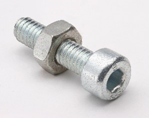
Image 1: Screw and Nut
Source: https://quizizz.com/admin/quiz/5f17c374c1a99b001b506a90/bolt-nut-assessment
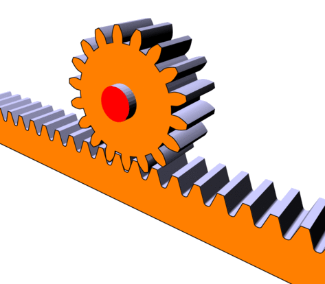
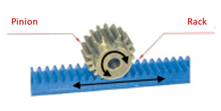
Rack & Pinion
The rack and pinion system transforms the rotational movement of the pinion into a translational movement of the rack or vice versa.
Advantages: There is no slippage during the transformation of this movement. The strength of this system is relatively high.
Disadvantages: The gears that are used may require extensive lubrication. This mechanism requires precise adjustment because of the teeth between the wheel and the rack. There is a lot of wear. It is not a cyclic movement; it is a finite movement (you must stop when you reach the end of the rack).
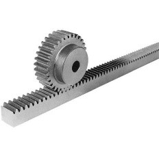
Image 2: Rack and Pinion
Source: https://www.indiamart.com/supertekengineers/industrial-gears.html
Example: Car steering, net tensioners (badminton net for example), adjustment mechanisms of some microscopes, camera tripods, etc.
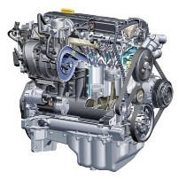
Image 3: Motor
Source : http://www.carbus46.ru/
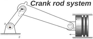
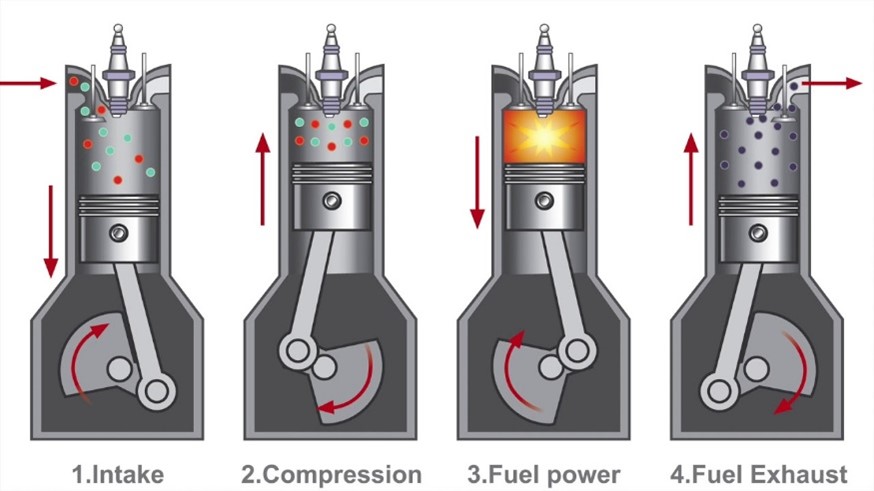
Crank & Rod system
The crank and connecting rod system transforms rotary motion into reciprocating motion (straight back and forth) and vice versa.
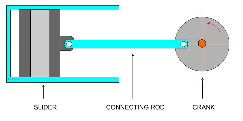
Advantages: This mechanism can operate at high speed.
Disadvantages: There is a lot of friction due to the many joints in this system. This requires a lot of lubrication.
Image 4: GIF Crank and Rod system
Source: https://technologystudent.com/cams/crkslid1.htm
Example: Petrol engines, diesel engines, pumps, medical respirators, steam locomotives, old sewing machines, spinning wheels, grinding wheels, etc.
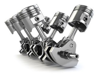
Image 5: Crank and Rod system in a motor
Source: https://elements.envato.com/fr/video-cinema-movie-multimedia-concept-a-row-of-vin-36K4C2D
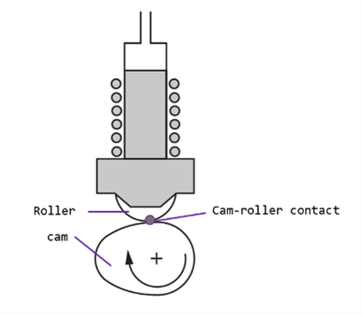
Cam and Roller System
The cam and roller system (also known as the cam and push rod system or guided rod) transforms the rotational movement of the cam into a reciprocating movement of the push rod.
Advantages:
The cam can be configured to vary the movement of the rod from one translational motion to another.
There is no slippage, the speed ratio is constant.
This system allows a considerable reduction in speed.
Disadvantages:
The rod must be guided in translation.
A return spring is usually required to allow the rod to rest continuously on the cam.
There is a risk of severe vibration if the cam rotates at high speed.
Image 6: Diagram Cam and Roller System
Source: https://www.tribonet.org/news/testing-of-cam-roller-follower-systems/
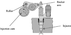
Example: Mechanical toys, mechanisms for controlling the opening and closing of valves in a car engine (camshafts and valves), sewing machines, etc.
Image 7: Cam and Roller in a System
Source: https://www.researchgate.net/figure/Injection-cam-rocker-arm-and-injector-system-4_fig1_258283537
| Advantages | Disadvantages | Characteristics | |
| Screw & Nut | -Allows important forces and pressures -Used for fine adjustments | -Generate friction -Can lead to guiding problems | Efficiency: ++ Speed: ++ Stability: +++ |
| Rack & Pinion | -No slippage -High strength | -Required fine adjustment -Finite movement | Efficiency:+++ Speed: ++ Stability: ++ |
| Crank & Rod system | -Operation well on high speed | -Poor efficiency (due to friction) | Efficiency: + Speed: +++ Stability: +++ |
| Cam and Roller System | -Constant speed ratio -Can lower the system’s speed | -Rod has to be guided -Risk of vibration at high speed | Efficiency:+++ Speed: + Stability: + |
Rack & Pinion
Presentation:
The main function of a rack and pinion system is to transform a rotational motion into a translational motion (or vice versa).
This system consists of a toothed wheel called a “pinion” and a toothed rod called a “rack”. When the pinion turns, its teeth mesh with the teeth of the rack and drive the rack in a translational motion.
Source: http://pstricks.blogspot.com/2020/03/systeme-pignon-cremaillere-en-3d-essai.html
Advantages:
- This type of mechanism allows to transform the movement without sliding between the parts.
- It is a reversible system.
- The strength of this system is relatively great.
Disadvantages:
- The gears that are used may require extensive lubrication.
- This mechanism requires precise adjustment because of the teeth between the wheel and the rack.
- There is a lot of wear.
- It is not a cyclic movement; it is a finite movement (you have to stop when you reach the end of the rack).
Example:
A rack and pinion system is used in the steering mechanism of cars.
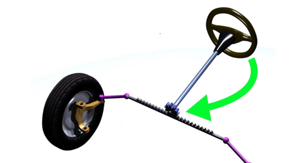
Source: https://fr.wikipedia.org/wiki/Direction_(automobile)
How to dimension this system?
Main operation:
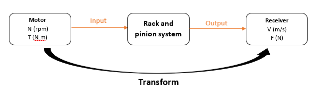
N : Rotation frequency in rpm (revolutions per minute)
T : Torque in m.N (newton-metre)
V : Speed in m/s (meter per second)
F : Force (Newton)
Geometry:
Reminders :
m : modulus
p: step
dpinion : pitch diameter of the pinion
Zpinion : number of pinion teeth
dpinion=m x Zpinion
Image 11: Rack and Pinion system
Source: ssi.stjo.lasalle.free.fr/content/fichiers/FS_1ere/%5BFS15%5D Les engrenages %5BPart_4%5D.pdf
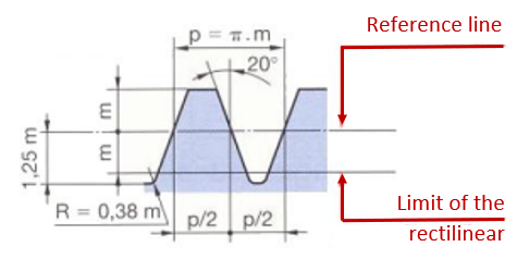
p = step
m = modulus
R = radius
Image 12: Pinion
Source: ssi.stjo.lasalle.free.fr/content/fichiers/FS_1ere/%5BFS15%5D Les engrenages %5BPart_4%5D.pdf
Mechanical characteristic:
Rotation: P = C . ω
With : P (W), C (m.N), ω (rad/s)
Translation : P = F . V
With : P (W), F (N), V (m/s)
Efficiency : Ps / Pe or Pu / Pa
With : Pu = Useful power
Pa = Absorbed power
The efficiency of this system is very good (>95%). It often takes the value 1 in mechanical models.
Rack speed :
Srack = Rpinion x ωpinion
Rack displacement :
Drack = Rpinion x Ꝋpinion
Srack in m/s
ωpinion : pinion rotation speed in rad/s
Rpinion in m
Ꝋpinion in m
System diagram:
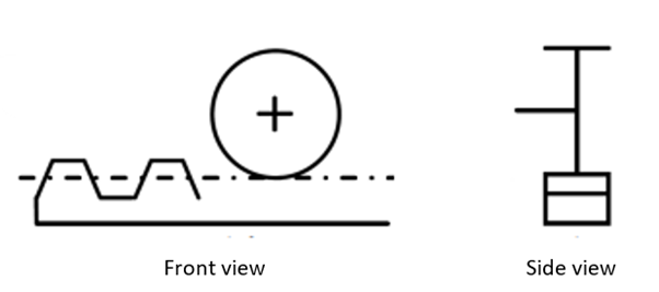
Image 14: System diagram
Source: ssi.stjo.lasalle.free.fr/content/fichiers/FS_1ere/%5BFS15%5D Les engrenages %5BPart_4%5D.pdf
Crank & Rod system
Presentation :
The connecting rod-crank system is a mechanical assembly that takes its name from the two mechanical parts that make it up: the connecting rod and the crank. This device transforms the reciprocating linear motion of the connecting rod end into a continuous rotary motion available to the crank (crankshaft), and vice versa.
Source: http://ajtco.free.fr/mecanique/cinematique/ex1cirdetail.html
This mechanism consists of three elements:
- The crank is connected by a rotary joint (crankshaft) to the frame and the connecting rod head
- Biella is connected to the crank and the piston pin
- The cross member or sliding nut is the element that prevents the transmission of lateral forces to the piston, making the connecting rod slide along a straight line; that connects the connecting rod to the piston, making the piston subject only to forces along the sliding axis
Alternatively, the connecting rod can be connected directly to the piston, without the use of the crossbar, in fact this is the classic case of a greater application of the mechanism.
Furthermore, depending on the way it is arranged, the sliding axis of the piston of the crank mechanism can be:
Centred, where the axis on which the piston slides intersects the axis of the drive shaft.
Off-centre or Oblique when this axis does not intersect the motor shaft, but is offset forward or backward.
Advantages and disadvantages of the slide-less mechanism :
With this system you have the advantage:
- For the same piston movement, the crank can turn in both directions.
- Doesn’t take up much space and supports high power (e.g. car)
- This mechanism can operate at high speed.
With this system, there is a disadvantage:
- Ovalization of the piston seat, this phenomenon is important especially in thermal engines or in systems where the treatment of a fluid is required, where the greatest possible sealing of the piston and the best reliability over time is sought, but it is of no importance in machines where this mechanism is only used to transform a movement from rotary to linear, such as those of circuit breakers.
- There is a lot of friction due to the many joints in this system.
- This requires a lot of lubrication.
Source: https://www.ornikar.com/code/cours/mecanique-vehicule/moteur
The crank and connecting rod above is the function of car pistons. The explosion in the upper cylinder drives the connecting rod and turns the system
How to dimension this system?
In the (x, y) plane of the following diagram, we can represent the movements of each part in real size.
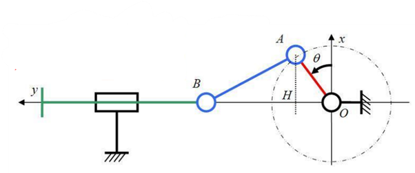
Connecting rod length : AB = L
Stroke : C = 2.OA = 2.R (radius)
Angular position : Ꝋ(t) = ω.t
Image 17: Plan of a connecting rod and crank system
Source: https://fr.wikipedia.org/wiki/Syst%C3%A8me_bielle-manivelle
The geometry depends of:
- The radius R=OA of the crank
- The length L=AB of the connecting rod
- The distance between the point O and the line of displacement of the point B
Calculation:
h(t) = OB
= OH + HB
= R.sin Ꝋ + L.cos(sin-1(R.cos Ꝋ/ L))
= R.sin Ꝋ + √(L2 – R2 cos 2 Ꝋ)
With Ꝋ(t) = ω.t
If we derive h(t) we obtain the speed and then by deriving the acceleration.
Special case:
- If Ꝋ(t) = 90° :
h(t) = OB = OA + AB + R + L
This is the highest position of B, called top dead center because its speed cancels to change its sign.
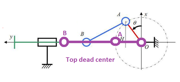
Source: https://fr.wikipedia.org/wiki/Syst%C3%A8me_bielle-manivelle
- If Ꝋ(t) = 270° :
h(t) = OB = BA – AO = L-R
This is the lowest position of B, called “bottom dead center”.
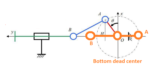
Source: https://fr.wikipedia.org/wiki/Syst%C3%A8me_bielle-manivelle
The distance between the two dead centers, which is 2R, is called the piston stroke.
Quiz
Test your skills!
Glossary
Crankshaft – is a mechanical part able to perform a conversion between reciprocating motion and rotational motion. In a reciprocating engine, it translates reciprocating motion of the piston into rotational motion, whereas in a reciprocating compressor, it converts the rotational motion into reciprocating motion. To do the conversion between two motions, the crankshaft has “crank throws” or “crankpins”, additional bearing surfaces whose axis is offset from that of the crank, to which the “big ends” of the connecting rods from each cylinder attach.
Electric motor – is an electrical machine that converts electrical energy into mechanical energy. Most electric motors operate through the interaction between the motor’s magnetic field and electric current in a wire winding to generate force in the form of rotation of a shaft. Electric motors can be powered by direct current (DC) sources, such as from batteries, motor vehicles or rectifiers, or by alternating current (AC) sources, such as a power grid, inverters or electrical generators. An electric generator is mechanically identical to an electric motor, but operates in the reverse direction, converting mechanical energy into electrical energy.
A gear – is a rotating circular machine part having cut teeth or, in the case of a cogwheel or gearwheel, inserted teeth (called cogs), which mesh with another (compatible) toothed part to transmit (convert) torque and speed. The basic principle behind the operation of gears is analogous to the basic principle of levers. A gear may also be known informally as a cog. Geared devices can change the speed, torque, and direction of a power source. Gears of different sizes produce a change in torque, creating a mechanical advantage, through their gear ratio, and thus may be considered a simple machine. The rotational speeds, and the torques, of two meshing gears differ in proportion to their diameters. The teeth on the two meshing gears all have the same shape.
Mechanics (from Ancient Greek: μηχανική, mēkhanikḗ, lit. “of machines”) is the area of mathematics and physics concerned with the relationships between force, matter, and motion among physical objects.[3] Forces applied to objects result in displacements, or changes of an object’s position relative to its environment.
Pinion – is a round gear—usually the smaller of two meshed gears—used in several applications, including drivetrain and rack and pinion systems.
Rack and pinion – is a type of linear actuator that comprises a circular gear (the pinion) engaging a linear gear (the rack), which operate to translate rotational motion into linear motion. Driving the pinion into rotation causes the rack to be driven linearly. Driving the rack linearly will cause the pinion to be driven into a rotation. A rack and pinion drive can use both straight and helical gears. Though some suggest Helical gears are noted for “quieter” operation, there is no science to support this theory. Helical racks while being more affordable, have proven to increase side torque on the datums, increasing operating temperature leading to premature wear. Straight racks require a lower driving force and offer increased torque and speed per percentage of gear ratio which allows lower operating temperature and lessens viscal friction and energy use. The maximum force that can be transmitted in a rack and pinion mechanism is determined by the tooth pitch and the size of the pinion as well as the gear ratio.
Reversible – Whose effect and cause can be reversed. Most electrical machines are reversible, i.e., instead of supplying electricity through a mechanical motor, they can vice versa transform electrical energy into mechanical work.
Rotation – is the circular movement of an object around an axis of rotation. A three-dimensional object may have an infinite number of rotation axes.
Translation – is a geometric transformation that moves every point of a figure, shape or space by the same distance in a given direction. A translation can also be interpreted as the addition of a constant vector to every point, or as shifting the origin of the coordinate system. In a Euclidean space, any translation is an isometry.
Wheel – In its primitive form, a wheel is a circular block of a hard and durable material at whose center has been bored a hole through which is placed an axle bearing about which the wheel rotates when torque is applied to the wheel about its axis. The wheel and axle assembly can be considered one of the six simple machines.
Wheel and axle – is a machine consisting of a wheel attached to a smaller axle so that these two parts rotate together in which a force is transferred from one to the other. The wheel and axle can be viewed as a version of the lever, with a drive force applied tangentially to the perimeter of the wheel and a load force applied to the axle, respectively, that are balanced around the hinge which is the fulcrum.