- Definition of a motion transformer
- Motion transformer types
- Focus: Rack & Pinion
- Focus: Crank & Rod system
- Quiz
- Glossary
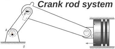
Crank & Rod system
Presentation :
The connecting rod-crank system is a mechanical assembly that takes its name from the two mechanical parts that make it up: the connecting rod and the crank. This device transforms the reciprocating linear motion of the connecting rod end into a continuous rotary motion available to the crank (crankshaft), and vice versa.
Source: http://ajtco.free.fr/mecanique/cinematique/ex1cirdetail.html
This mechanism consists of three elements:
- The crank is connected by a rotary joint (crankshaft) to the frame and the connecting rod head
- Biella is connected to the crank and the piston pin
- The cross member or sliding nut is the element that prevents the transmission of lateral forces to the piston, making the connecting rod slide along a straight line; that connects the connecting rod to the piston, making the piston subject only to forces along the sliding axis
Alternatively, the connecting rod can be connected directly to the piston, without the use of the crossbar, in fact this is the classic case of a greater application of the mechanism.
Furthermore, depending on the way it is arranged, the sliding axis of the piston of the crank mechanism can be:
Centred, where the axis on which the piston slides intersects the axis of the drive shaft.
Off-centre or Oblique when this axis does not intersect the motor shaft, but is offset forward or backward.
Advantages and disadvantages of the slide-less mechanism :
With this system you have the advantage:
- For the same piston movement, the crank can turn in both directions.
- Doesn’t take up much space and supports high power (e.g. car)
- This mechanism can operate at high speed.
With this system, there is a disadvantage:
- Ovalization of the piston seat, this phenomenon is important especially in thermal engines or in systems where the treatment of a fluid is required, where the greatest possible sealing of the piston and the best reliability over time is sought, but it is of no importance in machines where this mechanism is only used to transform a movement from rotary to linear, such as those of circuit breakers.
- There is a lot of friction due to the many joints in this system.
- This requires a lot of lubrication.
Source: https://www.ornikar.com/code/cours/mecanique-vehicule/moteur
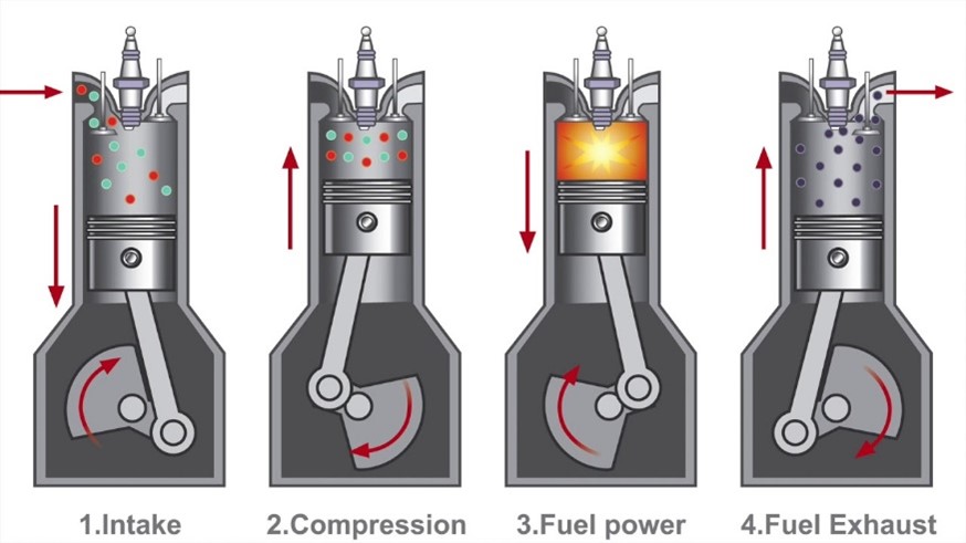
The crank and connecting rod above is the function of car pistons. The explosion in the upper cylinder drives the connecting rod and turns the system
How to dimension this system?
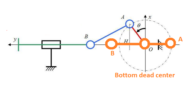
In the (x, y) plane of the following diagram, we can represent the movements of each part in real size.
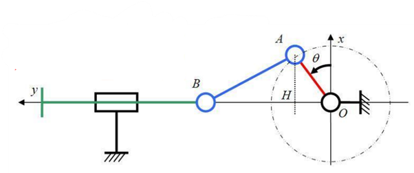
Connecting rod length : AB = L
Stroke : C = 2.OA = 2.R (radius)
Angular position : Ꝋ(t) = ω.t
Image 17: Plan of a connecting rod and crank system
Source: https://fr.wikipedia.org/wiki/Syst%C3%A8me_bielle-manivelle
The geometry depends of:
- The radius R=OA of the crank
- The length L=AB of the connecting rod
- The distance between the point O and the line of displacement of the point B
Calculation:
h(t) = OB
= OH + HB
= R.sin Ꝋ + L.cos(sin-1(R.cos Ꝋ/ L))
= R.sin Ꝋ + √(L2 – R2 cos 2 Ꝋ)
With Ꝋ(t) = ω.t
If we derive h(t) we obtain the speed and then by deriving the acceleration.
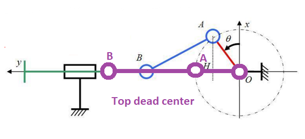
Special case:
- If Ꝋ(t) = 90° :
h(t) = OB = OA + AB + R + L
This is the highest position of B, called top dead center because its speed cancels to change its sign.
Source: https://fr.wikipedia.org/wiki/Syst%C3%A8me_bielle-manivelle
- If Ꝋ(t) = 270° :
h(t) = OB = BA – AO = L-R
This is the lowest position of B, called “bottom dead center”.
Source: https://fr.wikipedia.org/wiki/Syst%C3%A8me_bielle-manivelle
The distance between the two dead centres, which is 2R, is called the piston stroke.